20231118

knock sensor

“Knocking” occurs when the air-fuel mixture self-ignites prematurely. Sustained knocking causes damage primarily to the cylinder head gasket and cylinder head. The knock sensor identifies the high-frequency engine vibrations characteristic of knocking and transmits a signal to the ECU. The aim is to obtain the maximum energy yield by starting ignition as early as possible. Engines with a knock sensor can reduce fuel consumption and increase torque.


What is knock sensor?

The knock sensor monitors the combustion process in the engine. Its signal helps the engine control to prevent knocking combustion and therefore protect the motor/engine control. On this page we will provide you with various information, including how a defective knock sensor becomes noticeable, the causes that may lead to its failure, and how it can be tested in the workshop.

Important safety note The following technical information and practical tips have been compiled by HELLA in order to provide professional support to vehicle workshops in their work. The information provided on this website is intended for use by suitably qualified personnel only.

The knock sensor is located on the outside of the engine block. It is intended to record knocking noise in all engine operating states in order to prevent engine damage.

 Car knock sensor function


The knock sensor "listens out for" the structure-borne vibrations from the engine block and converts these into electrical voltage signals. The signals are filtered and evaluated in the control unit. The knocking signal is assigned to respective cylinder. If knocking occurs, the ignition signal for the respective cylinder is adjusted in the "late" direction until knocking combustion no longer occurs.


20231113

Wheel speed sensor

A wheel speed sensor (WSS) or vehicle speed sensor (VSS) is a type of tachometer. It is a sender device used for reading the speed of a vehicle's wheel rotation. It usually consists of a toothed ring and pickup.


Purpose

The wheel speed sensor was initially used to replace the mechanical linkage from the wheels to the speedometer, eliminating cable breakage and simplifying the gauge construction by eliminating moving parts. These sensors also produce data that allows automated driving aids like ABS to function.

Construction

The most common wheel speed sensor system consists of a ferromagnetic toothed reluctor ring (tone wheel) and a sensor (which can be passive or active).

The tone wheel is typically made of steel and may be an open-air design, or sealed (as in the case of unitized bearing assemblies). The number of teeth is chosen as a trade-off between low-speed sensing/accuracy and high-speed sensing/cost. Greater numbers of teeth will require more machining operations and (in the case of passive sensors) produce a higher frequency output signal which may not be as easily interpreted at the receiving end, but give a better resolution and higher signal update rate. In more advanced systems, the teeth can be asymmetrically shaped to allow the sensor to distinguish between forward and reverse rotation of the wheel.

A passive sensor typically consists of a ferromagnetic rod which is oriented to project radially from the tone wheel with a permanent magnet at the opposite end. The rod is wound with fine wire which experiences an induced alternating voltage as the tone wheel rotates, as the teeth interfere with the magnetic field. Passive sensors output a sinusoidal signal which grows in magnitude and frequency with wheel speed.

A variation of the passive sensor does not have a magnet backing it, but rather a tone wheel which consists of alternating magnetic poles produce the alternating voltage. The output of this sensor tends to resemble a square wave, rather than a sinusoid, but still increases in magnitude as wheels speed increases.

An active sensor is a passive sensor with signal conditioning circuitry built into the device. This signal conditioning may be amplifying the signal's magnitude; changing the signal's form to PWM, square wave, or others; or encoding the value into a communication protocol before transmission.


camshaft position sensor

 The camshaft sensor enables the engine control to determine the exact position of the crankshaft drive. This information is required to calculate the ignition point and injection point, among other things. On this page, you can find out how a fault on the camshaft sensor can manifest itself, and which steps should be taken during troubleshooting.


1. CAMSHAFT SENSOR FUNCTION: 

FUNCTIONAL      PRINCIPLE

The task of the camshaft sensor is to work with the crankshaft sensor to define the exact position of the crankshaft drive. Through the combination of both sensor signals, the engine control unit knows when the first cylinder is in the top dead point.

 This information is needed for three purposes:


(1)For the start of injection during sequential injection.

(2)For the actuation signal of the solenoid valve for the pump-nozzle injection system.

(3)For cylinder-selective knocking control.

 The camshaft sensor works according to the Hall principle. It scans a ring gear on the camshaft. The rotation of the ring gear changes the Hall voltage of the Hall IC in the sensor head. This change in voltage is transmitted to the control unit and evaluated there in order to establish the required data.

2.SYMPTOMS OF A FAULTY CAMSHAFT POSITION SENSOR: SYMPTOMS


A faulty camshaft sensor can cause the following symptoms:


(1)Starting difficulties

(2)Engine indicator lamp comes on

(3)Fault code is stored

(4)Control unit enters an emergency program


3. CAMSHAFT POSITION SENSOR FAULTY: CAUSE OF FAILURE

Reasons for failure of the camshaft sensor can be:


(1)Mechanical damage

(2)Break in the encoder wheel

(3)Internal short circuits

(4)Interruption in connection to the control unit


4. CHECKING THE CAMSHAFT POSITION SENSOR: TROUBLESHOOTING

TROUBLESHOOTING:

Check sensor for damage ✓

Read out the fault memory ✓

Check the electrical connections of the sensor wiring, the connector, and the sensor for correct connection, breaks, and corrosion.


1. Checking the connection line

Check the connection line from the control unit to the sensor using the ohmmeter. Remove the connector from the control unit and remove the sensor, check the individual cables for continuity. A circuit diagram is required for the pin assignment. Reference value: approx. 0 Ohm.

2. Checking the connection lines for short circuit to frame

Check the connection lines for short circuit to frame. Measurement between sensor plug and vehicle ground, control unit plug removed. Reference value: >30 MOhm

3. Checking the supply voltage

Check the supply voltage from the control unit to the sensor. Insert the control unit plug, switch the ignition on. Reference value: approx. 5 V (note manufacturer's specifications).

4.  Checking the signal voltage

Check the signal voltage. Connect the measuring cable from the oscilloscope and start the engine. A square wave signal must be displayed on the oscilloscope.


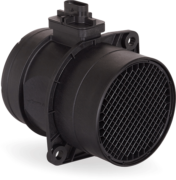
Mass airflow sensors

A growing focus on reducing CO2 emissions means that mass airflow sensors are becoming increasingly important in ensuring the optimum air fuel ratio.


Mass airflow sensors are positioned directly after the air filter in the intake manifold and supply information on temperature, humidity and intake air volume. Despite their highly compact construction they feature precision technology to capture information, which – together with other engine data – enables optimum engine management.

This data includes:

Intake air temperature
Intake air humidity
Intake air volume
In gasoline engines, mass airflow measurement is used in conjunction with other sensor readings to regulate the supply of fuel to the engine.

In diesel engines, mass airflow sensors are used to regulate the exhaust gas recirculation rate and calculate the maximum injection quantity.

Our mass airflow sensors are exceptionally reliable and highly capable of withstanding environmental factors. Their dynamic measurement ability makes an important contribution to reducing vehicle emissions.

4 pin relay wiring

Load Moment Indicator

  🏗️ Load Moment Indicator (LMI): The Crane’s Safety Brain 🔎 Introduction: The Silent Partner in the Cab Picture this: a 100‑ton beam...