It consists of two parallel plates separated
by an insulating material called the dielectric
• In the neutral state, both plates have an equal
number of free electrons
• When a voltage source is connected to the
capacitor, electrons are removed from one plate and
an equal number are deposited on the other plate
• No electrons flow through the dielectric (insulator)
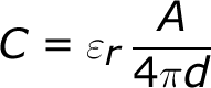
The capacitance of a capacitor -- how many farads it has -- depends on how it's constructed. More capacitance requires a larger capacitor. Plates with more overlapping surface area provide more capacitance, while more distance between the plates means less capacitance. The material of the dielectric even has an effect on how many farads a cap has. The total capacitance of a capacitor can be calculated with the equation:
Where ε
r is the dielectric's
relative permittivity
(a constant value determined by the dielectric material),
A is the amount of area the plates overlap each other, and
d is the distance between the plates.
Charging & Discharging of a Capacitor
Consider the following circuit.
Assume that the capacitor is fully discharged and the switch connected to the capacitor has just been moved to position A. The voltage across the 100uf capacitor is zero at this point and a charging current ( i ) begins to flow charging up the capacitor until the voltage across the plates is equal to the 12v supply voltage. The charging current stops flowing and the capacitor is said to be “fully-charged”. Then, Vc = Vs = 12v.
Once the capacitor is “fully-charged” in theory it will maintain its state of voltage charge even when the supply voltage has been disconnected as they act as a sort of temporary storage device. However, while this may be true of an “ideal” capacitor, a real capacitor will slowly discharge itself over a long period of time due to the internal leakage currents flowing through the dielectric.
This is an important point to remember as large value capacitors connected across high voltage supplies can still maintain a significant amount of charge even when the supply voltage is switched “OFF”.
If the switch was disconnected at this point, the capacitor would maintain its charge indefinitely, but due to internal leakage currents flowing across its dielectric the capacitor would very slowly begin to discharge itself as the electrons passed through the dielectric. The time taken for the capacitor to discharge down to 37% of its supply voltage is known as its Time Constant.
If the switch is now moved from position A to position B, the fully charged capacitor would start to discharge through the lamp now connected across it, illuminating the lamp until the capacitor was fully discharged as the element of the lamp has a resistive value.
The brightness of the lamp and the duration of illumination would ultimately depend upon the capacitance value of the capacitor and the resistance of the lamp (t = R*C). The larger the value of the capacitor the brighter and longer will be the illumination of the lamp as it could store more charge.
Energy stored by capacitor:
When a capacitor charging energy transferred from source voltage to capacitor.
When the capacitor is removed energy from source the potential deference across it's plate remain constant.
Since no current is required to maintain this potential deference. The capacitance store electron electric energy. This energy stores in electric fieldBetween the plates.
The energy stored by a fully charged capacitor.
Where is
W = symbol of energy
J = Unit if energy
Capacitor in series:
When capacitors are connected in series, the total capacitance is less than any one of the series capacitors’ individual capacitances. If two or more capacitors are connected in series, the overall effect is that of a single (equivalent) capacitor having the sum total of the plate spacings of the individual capacitors. As we’ve just seen, an increase in plate spacing, with all other factors unchanged, results in decreased capacitance.
Thus, the total capacitance is less than any one of the individual capacitors’ capacitances. The formula for calculating the series total capacitance is the same form as for calculating
parallel resistances:
When capacitors are connected in parallel, the total capacitance is the sum of the individual capacitors’ capacitances. If two or more capacitors are connected in parallel, the overall effect is that of a single equivalent capacitor having the sum total of the plate areas of the individual capacitors. As we’ve just seen, an increase in plate area, with all other factors unchanged, results in increased capacitance.
As you will no doubt notice, this is exactly the opposite of the phenomenon exhibited by
resistors. With resistors, series connections result in additive values while parallel connections result in diminished values. With capacitors, its the reverse: parallel connections result in additive values while series connections result in diminished values.


Well try too
ReplyDelete