Introduction
A MCB is a mechanical switching device which is capable of making, carrying and breaking currents under normal circuit conditions and also making, carrying for a specified time and automatically breaking currents under specified abnormal circuit conditions such as those of short circuit. In short, MCB is a device for overload and short circuitprotection. They are
used in residential & commercial areas. Just like we spend time to make a thorough check before buying appliances like washing machines or
refrigerators, we must also research mcbs
MCB COMPONENT
Actuator lever - used to manually trip and reset the circuit breaker. Also indicates the status of the circuit breaker (On or Off/tripped). Most breakers are designed so they can still trip even if the lever is held or locked in the "on" position. This is sometimes referred to as "free trip" or "positive trip" operation.
1. Actuator mechanism - forces the contacts
Together or apart.
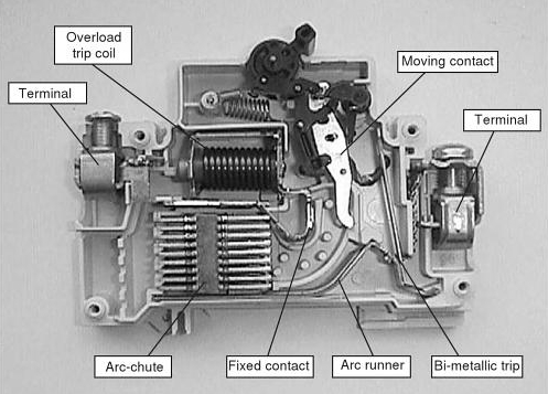
2. Contacts - Allow current when touching and break the current when moved apart.
3. Terminals
4. Bimetallic strip. .
5. Calibration screw - allows the
manufacturer to precisely adjust the trip
Current of the device after assembly
6. Solenoid
7. Arc divider/extinguishe
Working Principle
While the main purpose of this article is about selection of MCBs, it is worth summarizing the working principle of MCBs in brief.
MCB is a compact cased device that has an electro-mechanical mechanism inside that provides overload protection.
There are essentially three different mechanisms inside that provide overload protection:
Bimetallic Strip:
This arrangement is used in situations where a constant overload condition prevails over a long time in the connected circuit thus resulting in heating of bimetallic strip. Due to this the bimetallic strip deflects and causes the attached latch to be released. This causes the attached spring to get released and moving contactor open the circuit.
Magnetic Trip Coil:
This mechanism comes in force in case of a short circuit event. A short circuit event is associated with a sudden surge of a heavy short circuit current that tends to flow through the circuit. This sudden surge of short circuit current flows through a very sensitive magnetic trip coil inside MCB. This causes a sudden change in magnetic flux and activates the trip coil unit. Due to this, the plunger inside the coil deflects and releases the same latch point and subsequently the same release of spring and opening of the contactor and the circuit.
Manual Switching:
MCB also has an external ON/OFF switching option to manually break the circuit. This is used in cases of any maintenance / repair activities or for resetting of MCB and power in case of an already occured trip event.
Technical Specifications –
Selecting a Suitable MCB
From the technical specifications of an MCB it is possible to deduce which – if any – circuit
breaker types are basically suitable for the planned protection and switching task.
1. Terminal Block (Cable/Busbar)
Depending on the MCB model, various types of cables/lines (single/multi-core,
with/without core end sleeve) can be connected in combination with busbars.
2. MCB Type Label
Contains:
Manufacturer brand name - Siemens
MCB Order No. - 5SL6116-7
Indication of tripping
characteristic/rated current - C 16
Usability in an electric
supply network:- - 230/400 V AC
3. Quality Label Approval VDE
The product has been tested by an independent testing body and the quality label has been
approved. (Additional assurance for the end user.)
4. Switching Capacity of the Device in Ampere/Energy Limitation Class
The MCB shown has a switching capacity of Icn 6 kA, and satisfies the requirements of
Energy Limitation Class 3.
In accordance with the Technical Connection Requirements (TAB) for German network
operators, only MCBs with a rated switching capacity of min. 6 kA and energy limitation
class 3 are permitted for use in residential constructions.
5. Handle for Manual Actuation of the MCB
With integrated switch position indicator (I-ON/0-OFF):
• red identification for switch position ON
• green identification for switch position OFF
The main contact position may deviate from the handle position.
Main contacts may e.g. be in OFF position, although the handle is in ON position (trip-free).
Some MCBs have an additional mechanical display for the actual position of the main contacts.
6. Switching Symbol
Identification for easy recognition of the correct terminal type.
Shown here MCB terminals in single-pole version
The N conductor terminal is identified with the symbol ‘N’.
In multi-pole devices, a horizontal dashed line over the switching contact symbols identifies
the mechanical coupling of the switching poles.
7. Coupling Location for System Components
The coupling location for additional system components on the MCB ensures indirect trip-
ping of the MCB by forwarding the triggering command to the MCB contact system or by
transmitting the tripping information to the system component(s).
8. Manual Slide Operation for Quick Fitting System
Easy manual actuation of the MCB for toolless removal from the standard mounting rail.
Symbol of MCBs


Comments
Post a Comment
Hey guys if any problem has about Electrical engineering. You can message me , I will do my best for you